GENSTAR

General Digital is offering the GenStar III™ and GenStar IV™ concurrently to accommodate differing air traffic control needs and budgets.
The GenStar III has significant advantages over the now discontinued GenStar II™, while delivering a good value.
The GenStar IV offers the very latest technological advancements for busier air traffic control towers.
Inquire about options, accessories and customization, including panel mount enclosures.
-
Overview
Key Features
- Maintains compatibility with STARS infrastructure, tower video controllers, seismic-qualified mounting solutions and Statement of Work
- Available in two display sizes
- 19.0″ and 21.3″
- Sunlight readable standard
- LED backlit standard
- Use as a standalone device or employ VESA mount to attach to yokes, cradles, pedestals or articulating arms
- GenStar IV offers many never-before-seen advanced features
- Originally designed in 1998, GenStar I and upgrade GenStar II are well integrated into air traffic control towers around the country for the FAA’s STARS program
- Both current GenStar models offer drop-in replacement for legacy monitors
GenStar III & GenStar IV Comparison
GenStar III™ | GenStar IV™

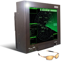
GenStar III
General Digital’s GenStar line of mountable sunlight readable LCD monitors was designed specifically to meet the stringent optical and operational requirements of the FAA’s Standard Terminal Automation Replacement System (STARS) program. As such, our specialized displays are ideally suited to meet other Air Traffic Control Tower applications, as well.
GenStar III and GenStar IV feature many advanced components and industry firsts:
- High performance 19.0″ and 21.3″ displays and video controllers
- Sunlight readable LED backlight and intelligent LED controller designed by General Digital
- Intelligent Backlight Controller™ prevents critical failures, display brightness control, monitors hardware performance and more (GenStar III)
- Microprocessor-controlled backlight cooling system (GenStar III)
- Software utilities that analyze performance/failure data to facilitate failure diagnosis and service
- Display enhancements, including an optically bonded contrast filter
- Field-replaceable AC power supply and cooling fans
- UL60950-1 and FCC Class A Certified
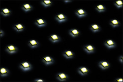
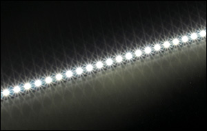
In most commercial applications, LED backlights are configured to drive their LED rails in a serial manner. While this technique is inexpensive and easy to implement, its downfall is that a single LED failure will render an entire rail inoperable—a catastrophe to mission-critical and safety-critical applications such as Air Traffic Control.
The GenStar LED rails utilize a serial-parallel design whereby the LEDs are driven in groupings of four, while the LED groups themselves are driven in a parallel manner. Using this approach, a single LED failure will only affect its immediate grouping, leaving the remaining groups of LEDs unaffected and fully operational.
Standalone/Mountable High Brightness Air Traffic Control Tower Monitors
Features GenStar III GenStar IV Display Size 19.0" 21.3" 19.0" 21.3" Resolution 1280 x 1024 1600 x 1200 1280 x 1024 1600 x 1200 Brightness, Maximum
(dependent upon filter)1000–1390 Nits 900 Nits 1240–1390 Nits 670–1900 Nits Backlight Type LED LED LED LED Enclosure Standalone/Mountable or Panel/Console Mount GenStar
Data SheetDownload GenStar
Control DrawingDownload Download — Download Ceiling Mount Articulating Arm
Control Drawing (Fits All)Download Panel Mount Adaptor Bracket
Control Drawing (Fits All)Download Tilt/Swivel Base
Control Drawing (Fits All)Download GenStar III In Depth
- Two display choices:
- 19.0″, 1280 x 1024 resolution
- 21.3″, 1600 x 1200 resolution
- LED backlights provide:
- Sunlight readable brightness
- Low power consumption
- Long life
- Advanced LED backlight controller
- Intelligent USB/OSD controller to tailor performance of system variables, including:
 Upgrade boot-load firmware in the field
- Over temperature corrective action
- Backlight brightness
- Minimum and maximum setpoints
- Brightness dimming
Enclosures
- Weighted specifically to match seismically-certified STARS ceiling mounts, yokes and pedestal stands
- Field-replaceable cooling fans and power supply
- Front accessible, intuitive to operate, user control
- Matte black finish to reduce reflections
The rugged aluminum enclosures of the GenStar III is designed to withstand the rigors of commercial, industrial, and military (COTS) environments alike. It is completely coated with Iridite® to provide protection from corrosion and improve shielding properties, where parts make contact with one another. All external surfaces are finished with a durable black powder coat. The enclosure can be adapted to support alternate display sizes and resolutions.
Video Controller
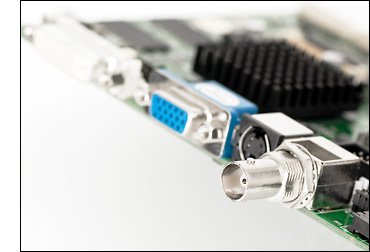
Internal to our LCD monitor is an LCD controller that converts EIA-RS-343 compatible analog RGB color video signals into digital signals required to drive the display. The controller has been customized to support a combination of seven STARS-compliant controllers (TSI 1000, TSI 1100T, TS4000e-LR, RACD, RACD2, RACD3 and RACD4) on two host platforms (SPARC and x86 Processors), while maintaining the ability to switch between any two combinations in less than 650ms.
The controller provides intuitive operation of its controls and calibration through the use of a membrane pad and a series of on-screen menus. All models support the following display image controls: auto and manual setup, brightness, contrast, horizontal position, vertical position, tuning, size, individual RGB adjust, image expansion on/off, system information, run-time counter, and signal level. Advanced features are supported on a selective basis (image rotate and invert, audio controls, advanced scaling).
- Compatible with all STARS-approved video controllers & video modes/timings
- Supports EIA-RS-343, Separate, Composite and Sync-On-Green video
- Custom firmware to support 650 ms switch time between primary and secondary video sources
- Ensures ATC operators can maintain airspace safety even after critical tower computer failure
Mounting Options
The GenStar III enclosure is designed to be used either as a portable display that can be carried from one location to another, or mounted using the supplied mounting holes located on the rear and sides of the enclosures. This facilitates the integration of standard or custom pedestals, yokes, cradles, or articulating arms. The monitors also accept all STARS-compliant ceiling mounts, yokes and gyroscopic desktop pedestal stands. The enclosures are specifically weighted and balanced so as to maintain the seismic certification when mounted to aforementioned STARS approved mounts. Speak with one of our Sales Engineers for the best mounting option for your application.
GenStar IV In Depth
As with previous incarnations, the Genstar IV remains a true drop-in replacement for existing TDM displays.
The new User Interface Display (UID) provides users with an intuitive means to configure performance, view status/faults and calibrate/control without having to block flight-critical data on the main display with an On-Screen Display (OSD).
HDMI, DisplayPort and DVI ports have been added in conjunction with the ARGB port to allow additional flexibility in supporting video sources.
Enhanced Backlight
Depending on the model, the Genstar IV features either an enhanced edge-lit LED backlight or direct-lit LED backlight. The backlights, in conjunction with General Digital’s LED controller, achieve a display brightness from 600 (to comply with STARS Statement of Work) to >1500 nits, with a dimming ratio of >1000:1. The backlights are controlled via PWM, allowing precise and flicker-free brightness control. The MTBF (half brightness life) of the LEDs exceeds 100,000 hours.
User Interface Display (UID)
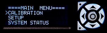
The Advanced Display Interface System (ADIS) of the GenStar IV takes user control to the next level through the integration of a separate character display to configure performance, monitor health and control the its behavior. The programmable display/keypad eliminates the OSD, keeping the main screen clear for data. It allows the user to access OSD controls, select preferred auto-dimming algorithm and brightness zones, configure alarm reporting, and more. Passcode access limits advanced settings to authorized technicians only.
Adjust system parameters, view system variables, and receive warnings or faults (e.g., LED backlight over temperature, fan failure, and power supply faults).
OSD Functions
Main display On-Screen Display (OSD) menu can be accessed via the character display to avoid blocking mission-critical flight information on the main display.Backlit Silicone Keypad
Seven white backlit keys: up, down, left, right, center, top programmable and bottom programmable. These keys have 16.7 million color choices and 255 steps of brightness ranging from 0% to 100% brightness, and can be set to automatically dim with main display or dim when inactive.Status LEDs
Three tri-color (red, green, yellow) status LEDs.Rotary Encoder Brightness Control
Precisely control the backlight brightness. Adjustable resolution.
Ambient Light Sensor

The GenStar IV boasts dual ambient light sensors to ensure that the display stays at the optimal brightness for the user. The sensors are located on either side of the monitor, ensuring that localized shadows will not impact performance. The ambient light sensor control is firmware-based and can be tailored to meet each specific customer’s needs. Settings can be changed on the fly through the monitor’s UID control panel.
Internal Sensors
Internal sensors are monitored by the control circuitry within the Genstar IV to ensure that the monitor operates within its specifications and prevents critical failures. The controller polls thermal/optical sensors, fan speed, the LED controller, video controller, and power supply for operating status. As needed, the controller can take actions such as increasing fan speed, adjusting brightness or notifying the user of potential issues through the UID.
USB Connectivity
A USB port on the back of the system allows the monitor to be connected to any PC. The connection allows for flash-upgrading of all embedded controller firmware (OSD, Modular Power Supply, Video, LED Backlight, Smart Fan) within the monitor, as well as access to system performance data and user-configurable settings. Monitor performance can be tailored or upgraded in the field without requiring return to the factory.

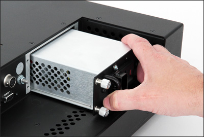
Field-Replaceable Power Supply
The GenStar IV power supply features a modular field-replaceable 100 Watt power supply featuring onboard monitoring of AC/DC power, output current and component temperature. Rear-mounted cooling fans are field accessible for replacement when the user is notified via the UID.
The new power supply features a modular, field-replaceable, power factor-corrected, fully enclosed “brick” that slides in and out of the monitor on alignment rails. When installed, the power supply brick mates with a General Digital-designed circuit board responsible for conditioning, filtering and distributing the power to the other monitor electronic subassemblies. Circuitry on this PCB is responsible for making the power supply meet the inrush and harmonics requirements of FAA-G-2100H and FAA-STD-019E. The brick is mechanically secured in place with captive fasteners located on the power supply’s bezel/mounting bracket.
The supply is capable of running at 50° C without derating. Limits for voltage and current are pre-programmed by General Digital at the factory. In the event that these limits are exceeded, the power supply will automatically disconnect power from the monitor to prevent any critical harm from occurring to the electronics. In addition, a failure signal is sent to the intelligent OSD controller, which triggers a status LED on the front bezel to provide a visual indication of the failure to the user. In addition, the failure is saved in nonvolatile memory. A verbose description of the failure can also be retrieved real time from the Advanced Display Interface System (ADIS).
The supply also monitors other performance; such as the temperature of its critical components, the input and output voltage health, the operating current in use, and the health of the AC and DC power. All of this data is shared with the intelligent OSD controller to be further shared on the ADIS.
- Modular, field-replaceable, fully contained, power supply brick
- Universal input 85–264 VAC single phase 47–63 Hz
- Power factor correction to 95% under full load
- EMI filtered from AC harmonics
- EMI shielded to meet FCC Class A
- Inrush current limited to meet FAA-G-2100H
- Temperature monitoring of critical components
- Output current monitoring
- Power health monitoring for both DC and AC
- Captive thumb screws for ease of service and secure mounting
- AC cable strain relief
- Built-in fuse holder
- Power switch
- Operating temperature range of -40° to +85° C
- Designed to meet FAA-G-2100H, FAA-STD-019E, UL60950, and FCC class A
Advanced Bootload System
The GenStar IV contains four major controller boards:
- Video Controller
- Smart Fan Controller
- LED Backlight Driver
- OSD Controller
All four of these boards (excludes OEM versions of LED Controller) can be bootloaded via the OSD controller USB (virtual serial port) port. The GenStar IV has been designed to partially run on USB bus power to simplify programming. The following features are available when powered from the USB bus:
- User Interface Display – Fully operational.
- Fan Controller – Bootload firmware, will not power fans.
- LED Backlight Driver – Bootload firmware, will not drive LED backlights.
- OSD Controller – Bootload firmware, fully operational, all I2C devices powered.
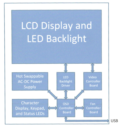
All boards are bootloaded using the General Digital Advanced Bootloader Application (ABA). This application simplifies bootloading to a few easy steps within the application. This eliminates any inconvenient procedures, such as power cycling a unit or keying precise button combinations. The union of effective bootloading and versatile hardware allows the user to reconfigure a system’s behavior entirely, without ever leaving the field. The ABA is a .NET utility, which is compatible with Windows® platforms.
Front Enclosure
Dimensions
The GenStar IV enclosure had been intentionally designed to maintain the same height and width dimensions (17.00″ x 19.50″ ) as its predecessors, the GenStar II and GenStar III. The depth has been decreased from 6.5″ to 4.5″. The monitor also includes the same ¼-20 x 0.31″ deep threaded mounting holes, in 4 places on the left and right sides, as the GenStar II and GenStar III, making it backwards compatible with the STARS-approved pedestal mount, ceiling mount and articulating arm. In addition, General Digital’s Panel Mount (Console Mount) Adaptor Bracket (P/N 90-1204-012) is also compatible. Mechanically, the new monitor is a “drop-in” replacement for its predecessors.
Construction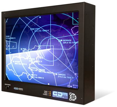
The front bezel is machined from a solid piece of ½” thick 5052-H32 aluminum to provide a stylish and aesthetically pleasing appearance. The corners are rounded to remove any sharp points and to ensure user safety. The corner radii are finished such that they precisely match the radius on the corners of the rear enclosure when the assembly is completed. The bezel is finished with a matte black powder coat finish to minimize reflections.
Display Cutout
The cutout for the LCD is chamfered at 45° to ensure that the panel can be viewed from extreme angles without obstruction.User Access Panel
A second cutout is provided in the front bezel to provide access to the User Interface Display’s (UID) User Access Panel. The character-based display is covered by a piece of protective glass which can be configured with antiglare (AG) or antireflective (AR) or AR/AG treatments.Keypad
A 7-button keypad is accessible on the front bezel to navigate the User Access Panel, and can also be programmed to function as “hot keys” to control dedicated functions such as Brightness Up/Down, Contrast Up/Down, or to manually activate/de-activate the UID.Backlight Brightness Potentiometer
Users can control the brightness of the LED backlight by using the front-accessible potentiometer to control the brightness over a full range from fully off to 100% on. Brightness ranges and limits can be pre-programmed.
Status/Fault LEDs
Cutouts in the front bezel are provided for 3 tri-state LEDs that function as visual status and warning indicators for users. The LEDs are used to report operational status and faults for the power supply (Power Good, Invalid Power, No Power, etc.), video controller (e.g., Standby Mode), internal monitor temperature (Temp. Good, Over Temp., etc.) and fans (Fan Failure). Additional LEDs may be added as an option. The Status LEDs will function in the same manner as the GenStar II.
Ambient Light Sensors
A pair of light sensors are installed in the front bezel facing outward to sense the ambient light conditions. Feedback from these sensors is used by the intelligent OSD board to automatically control the backlight brightness when placed in the Auto mode. Two sensors are provided to minimize the potential of shadows or other obstructions providing false or inaccurate light readings. The ambient light sensors can be disabled so that the backlight brightness can only be controlled manually.
Power Button (Optional)
A DC power switch can be added to the front bezel. This switch will enable/disable DC power to the internal electronics at the power supply. It will not disconnect AC power. When the DC power is OFF, the power supply goes into Sleep mode.Logo
The customer logo can be silkscreened on the front bezel, provided authorized artwork is provided to General Digital in advance. This option eliminates the need for the customer to contract and provide General Digital with decals or metal medallions. However, if these methods are still preferred, we can modify the bezel to mill a recess for the logo.
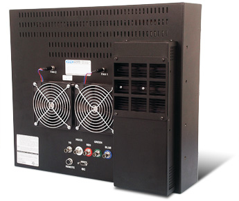
Rear Enclosure
Construction
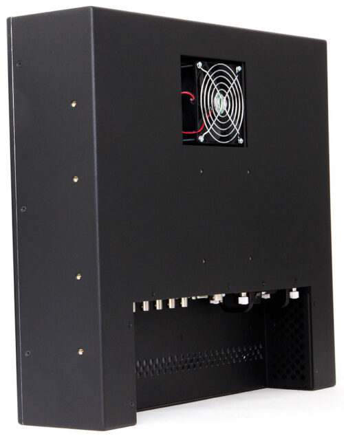
The rear enclosure is constructed from 0.090″ thick 5052-H32 aluminum. The corners are rounded to remove any sharp points and to ensure user safety. The corner radii are finished such that they precisely match the radius on the corners of the front bezel when the assembly is completed. The enclosure is finished with a matte black powder coat finish to minimize reflections.Connector Panel
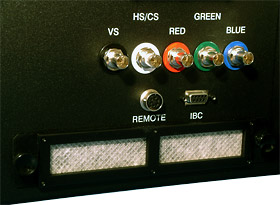
Unlike the prior versions of the GenStar, the GenStar IV has the I/O connector panel installed in a downward facing recess in the rear enclosure. The interface connections for the video I/O, Remote Brightness control, and USB/Maintenance port are distributed on this panel. A summary is provided below.The modular, field-replaceable, power supply brick, its fuse and the optional AC Power ON/OFF switch are also located on the connector panel.
Power Supply
A modular, field-replaceable, fully enclosed power supply brick is also accessible from the connector panel. The power supply fuse is accessible from within the CORCOM filter. The power supply is secured within the rear enclosure by external captive hardware mounted to the power supply mounting bracket. A locking restraint for the power cord is also provided to ensure the AC power cord does not become accidentally detached.On/Off Switch
A rocker switch is provided in the connector panel to activate and terminate the AC power.Ground Lug
A ¼” ground lug, in accordance with FAA-STD-19E and FAA-G-2100H is located on the connector panel. Optionally, the ground stud can be upgraded to a larger (e.g., 5/16″) lug.Cooling Fan(s)
A field-replaceable, recessed cooling fan is located on the rear enclosure to exhaust hot air out of the enclosure cavity. Easy to install replacement fan assemblies will be available for purchase from General Digital. Cool air is drawn through the electronics from ventilation holes located in the lower rear section of the enclosure and connector panel area. Users must be careful not to obstruct the ventilation holes.
Video Controller

Internal to our LCD monitor is an LCD controller that converts EIA-RS-343 compatible analog RGB color video signals into digital signals required to drive the display. The controller has been customized to support a combination of seven STARS-compliant controllers (TSI 1000, TSI 1100T, TS4000e-LR, RACD, RACD2, RACD3 and RACD4) on two host platforms (SPARC and x86 Processors), while maintaining the ability to switch between any two combinations in less than 650ms.
The controller provides intuitive operation of its controls and calibration through the use of a membrane pad and a series of on-screen menus. All models support the following display image controls: auto and manual setup, brightness, contrast, horizontal position, vertical position, tuning, size, individual RGB adjust, image expansion on/off, system information, run-time counter, and signal level. Advanced features are supported on a selective basis (image rotate and invert, audio controls, advanced scaling).
- Compatible with all STARS-approved video controllers & video modes/timings
- Supports EIA-RS-343, Separate, Composite and Sync-On-Green video
- Custom firmware to support 650 ms switch time between primary and secondary video sources
- Ensures ATC operators can maintain airspace safety even after critical tower computer failure
Mounting Options
Two types of mounting are provided on the rear enclosure assembly.
VESA Mounting
A 100 mm x 100 mm VESA mounting pattern is provided on the rear enclosure to support a variety of industry standard and third-party mounting devices. Optionally, General Digital can add support for a 100 mm x 200 mm mounting pattern; however, this will require a redesign of the power supply enclosure to eliminate conflicts for the mounting studs.Side Mounting
The monitor also includes the same ¼-20 x 0.31″ deep threaded mounting holes, in 4 places on the left and right sides, as the GenStar II and GenStar III, making it backwards compatible with the STARS-approved pedestal mount, ceiling mount and articulating arm.Other Mounting Options
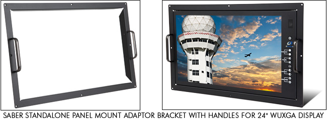
Panel Mount Adaptor
The GenStar IV is compatible with the GenStar II/III Panel Mount (Console Mount) Adaptor Bracket (P/N 90-1204-012). The adaptor mounts using the side mounting holes.
Slat Wall Mount Adaptor
General Digital can design a slat wall adaptor bracket to attach to the GenStar IV using either of the two mounting options provided. General Digital would need to know the type of slat wall, the manufacturer and the distance that the monitor would be mounted from the wall. Third-party adaptors may also be available to attach to the VESA mount.Other Air Traffic Control Monitor Choices
Saber Standalone/Saber Standalone Solar

In addition to the GenStar line, our mountable standard luminance Saber Standalone and high bright Saber Standalone Solar LCD monitors, with and without touch screens, are designed to provide Air Traffic Control Specialists with static and dynamic data regarding weather and other safety-critical operational data.
Our Saber Standalone family of industrial monitors are designed to be used where portable displays are required and can be carried conveniently from one location to another. Also used as video information displays for Naval air traffic control, their rugged enclosures are designed to provide years of durable service in demanding environments.
While constructed to be both rugged and portable, all of our standalone monitors can also be configured in rack mount and panel mount enclosures. Saber Standalone mountable LCD monitors come supplied with mounting holes on the rear and sides of the paneling; this allows easy integration into standard or custom pedestals, yokes, cradles or articulating arms. Because there is a wide variety of mounting options available, we recommend speaking with one of our Sales Engineers to determine which mounting option best fits your application.

Standalone/Mountable Standard Brightness Air Traffic Control Tower Monitors
Features Saber Standalone Saber Standalone/L22 Saber Standalone/L24 Display Size 17.0" 21.5" 24.0" Resolution 1280 x 1024 1920 x 1080 1920 x 1080 Brightness (Maximum) 350 Nits 300 Nits 300 Nits Backlight Type LED LED LED Enclosure Standalone/Mountable or Panel/Console Mount Data Sheet Download Control Drawing Download Download Download Panel Mount Adaptor Bracket Option — Download Download Comparison Chart Saber Standalone vs Commercial-Grade LCD Monitors Standalone/Mountable Sunlight Readable Air Traffic Control Tower Monitors
Features Saber Standalone Solar Saber Standalone Solar Saber Standalone Solar/LS19 Saber Standalone Solar/LS20 Saber Standalone Solar/LS22 Saber Standalone Solar/LS24 Saber Standalone Solar/LS24 Display Size 15.0" 17.0" 19.0" 20.1" 21.5" 24.0" 24.0" Resolution 1024 x 768 1280 x 1024 1280 x 1024 1600 x 1200 1920 x 1080 1920 x 1080 1920 x 1200 Brightness
(Maximum)600 Nits 932 Nits 1560 Nits 900/1300 Nits 525/695
Nits668/893
Nits1000 Nits Backlight Type LED LED LED LED LED LED LED Enclosure Standalone/
VESA Mount
or
Panel MountStandalone/
VESA Mount
or
Panel MountStandalone/
VESA Mount
or
Panel MountStandalone/
VESA Mount
or
Panel MountStandalone/
VESA Mount
or
Panel MountStandalone/
VESA Mount
or
Panel MountStandalone/
VESA Mount
or
Panel MountData Sheet Download Download Download Download Download Download Pending Control Drawing Download Download Download Download Download Download Pending Panel Mount Adaptor Bracket Option — — — Download Download Download Download Comparison Chart Saber Standalone Solar vs. Commercial-Grade LCD Monitors
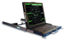
SlimLine 1U
Our rack-mounted SlimLine 1U LCD monitor/keyboard/trackball is used to provide system support and terminal weather data. Cleverly combining an LCD monitor, keyboard and trackball in one unit, the SlimLine 1U is considered the “perfect” complement to rack mount environments.
- Use with computer as a rack mount or standalone monitor/keyboard
- Low power (+12 Vdc) consumption
- Total design control facilitates customization
- Standalone, internal and rack mount power supplies available
- Cable management system available
- Front-mounted CD-RW, DVD-RW or Blu-ray drives available
- Optional audio add-on board provides volume control for stereo speakers
Flip-Up LCD with Keyboard High Brightness Air Traffic Control Tower Monitor
Features SlimLine 1U Display Size 19.0" Resolution 1280 x 1024 Brightness (max.) 1000 Nits Backlight Type LED Enclosure Rack Mount Flip-up Display with Keyboard Data Sheet Download Control Drawing Download The Background on Backlights
General Digital displays incorporate the latest in LED backlight technology, while providing cool and efficient illumination. Available technologies include the following:
OEM LED Backlight
Utilizing the display manufacturer’s integrated OEM LED backlight system provides the most cost-effective solution, while providing adequate readability under all conditions. A maximum brightness of 900 nits at the LCD surface, and a dimming ratio of 100:1 from 1% to 100%, is achievable.
Edge-lit LED Backlight
General Digital can replace the OEM LED backlight system with our custom-designed LED rails, using the latest in LED technology to provide an increase in luminance over the OEM system. Our backlight options provide a longer MTBF, and extended support is available for replacement parts. A maximum brightness of 1200 nits is achievable. When driven by General Digital’s LED controllers, a dimming ratio of >1000:1 is achievable, with a stable minimum brightness of ~1 nit.
Direct-lit LED Backlight
General Digital replaces the OEM LED backlight system with our custom-designed direct backlight system that can increase the maximum brightness to 1900 nits. This system also allows for a filtered air wash system that cools the backlight and rear surface of the LCD, increasing the resistance of the LCD to solar loading. External filters need to be added to the monitor to prevent external airborne stimuli from being introduced into the backlight from the air wash. Our backlighting options provide a longer MTBF than the OEM backlights, and extended support is available for replacement parts. When driven by General Digital LED controllers, a dimming ratio of >1000:1 is achievable, with a stable minimum brightness of ~1 nit.
Dimming
Although the OEM specification claims a 100:1 dimming ratio, General Digital backlights (both edge-lit and direct-lit), a dimming ratio of >1000:1 is achievable using our LED custom controller. Our testing has been able to achieve brightness as low as 0.4 nits.
Optical Enhancements Improve Readability
An added bonus of the current GenStar product line is the integration of General Digital’s suite of optical enhancements, which increase display contrast/clarity and reduce specular/diffuse reflections. Contrast improvements yield a deeper black background that makes data stand out in poor viewing conditions. Innovative use of light-diffusing technologies minimizes the adverse impact of glare and reflection.
OEM Antiglare Coating
Utilizing the display manufacturer’s integrated OEM antiglare coating eliminates reflections of objects that may otherwise detract from the information being displayed on screen. The GenStar can be equipped with an optically bonded glass overlay that has a mechanical etch of 72 gloss ±10 gloss points.
Antireflective Coating
Utilizing special coatings, broadband destructive wave interference can reduce reflections by as much as 93% at 580 nm, rather than the simple obscuration of the antiglare treatment.
Antiglare/Antireflective Coating
This includes a combination of both technologies, providing not just the physical elimination of reflection, but the obscuration of any remaining reflections.
Contrast Enhancing Filters
General Digital uses standard float glass on the GenStar; however, we have a variety of contrast filter options available. Speak with a Sales Engineer for more information.
Optical Bonding
The typical GenStar configuration features an overlay that is directly adhered to the display. This improves both the optical performance and the durability of the assembly. General Digital’s proprietary bond formulation was specifically designed with the STARS program in mind. Using an optically clear adhesive that is index matched to the refraction of the display and the overlay, we are able to greatly reduce internal reflections and improve a display’s brightness, luminance and ability to withstand harsh environmental testing requirements.
Options & Accessories

A myriad of display enhancements and services are available, such as:
- Antireflective coatings/antiglare etching
- Night Vision Goggle-compatible displays
- Sunlight readable displays
- Optical bonding
- Film laminations
- Touch screens
 EMI/RFI filters
- Display heaters
- Vandal shields
- Custom controls
- Custom bezels and enclosures
- Smart Card (CAC) readers
- Memory card readers
- Fiber Optics
- Private labeling
- Extended warranties
- Keyboards, power supplies, cables and more
- Programmable backlight/thermal controllers for optimal brightness/temperature conditions
Please consult a Sales Engineer to discuss your specific needs or ideas.
Configuration Control for Extended Life Cycle
We at General Digital are completely responsible for the design and construction of our products, allowing us to maintain nearly total control of their future. To that end, we gladly offer our engineering services to customers who require special customization of our devices to meet their commercial, industrial, marine or military requirements.
Our experience supporting Department of Defense programs has taught us the value of designing products with foresight so that they can be manufactured, serviced and upgraded for many years.
Though the market introduces new innovations and product upgrades at an alarming rate, our product management team knows the importance of proactive customer notification. Thus, we can offer product adaptation with similar or equivalent performance before designs become obsolete, thereby extending the product life cycle.
Please consult a Sales Engineer for additional details.
-
Design Your Display
Below you will find a breakdown of the GenStar model number, which references the key elements of your monitor.
Family Size/Resolution Display Video Controller Keyboard Enclosure Overlay Power Supply UB aab ccc(c) ddd ee ff gg hijj The Family category defines the base configuration, where…
UB = GenStarCan’t find a perfect fit? Use the form below to request a display tailored to your requirements. A Sales Engineer will contact you shortly to discuss your project.
-
Downloads
General Digital designs and manufactures scores of different monitor configurations each year, making the creation of technical documentation for each configuration impractical. We efficiently combine data into a select few documents, which answer most questions that customers typically ask. Please feel welcome to request any information not found here.
Utilities are available to all visitors, and can be used for a variety of LCD monitor applications.
User’s Manuals and Calibration & Setup Guides are available for customers only.
Product Drivers are available for customers only.
If you have lost the passwords provided with your product, please contact us right away.
-
Gallery
The photos below represent a small sampling of General Digital’s standard and custom GenStar LCD products. They serve to illustrate the many display sizes and mechanical configurations we offer, as well as standard and custom design features, capabilities and options. Click the thumbnails to view full-size photos.
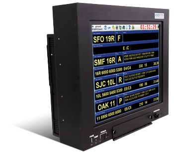
GenStar III
GenStar III 19.0

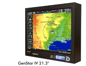
GenStar IV
GenStar IV 21.3


 with programmable display and keypad")

GenStar Accessories
Options for All GenStar Models


-
Videos
Watch the videos below to learn more about technologies used in the GenStar monitors, and display services General Digital offers for most monitors, whether built by us or another manufacturer.
GenStar IV – 360 Degree View (2:03)
Get a look at the GenStar IV from every angle and the space-saving features it incorporates over its predecessors. The GenStar product line is designed and built specially for air traffic control towers and other navigation industries.
GenStar IV – Daisy Chaining (0:35)
By driving multiple GenStar IV monitors from a single source, they can be daisy chained, which reduces clutter and expense.
GenStar IV – Removable Power Supply (0:44)
The GenStar IV power supply is internal to the unit, making it 2 inches slimmer than previous models. And it’s removable for in-the-field maintenance/replacement. It’s also FAA-G-2100H compliant and capable of 50° C operation without derating.
GenStar IV – Connector Panel (0:30)
An quick look at the space-saving connector panel incorporated into the latest iteration of the GenStar, a sunlight readable monitor built for air traffic control towers and other navigation industries.
GenStar IV – User Interface Display (0:52)
The User Interface Display (UID) on the GenStar IV air traffic control tower monitor provides users with an intuitive means to configure performance, view status/faults and calibrate/control without having to block flight-critical data on the main display with an On-Screen Display (OSD).
Industrial LED Backlight Architecture (2:38)
The following animation demonstrates the value and benefit of using an industrial-grade LED backlight designed with series-parallel architecture rather than a pure series approach found in traditional commercial-grade backlights.
Optical Characterization Services (2:16)
Unlike your phone, a display’s position cannot easily be adjusted to increase readability in direct sunlight. General Digital’s Optical Characterization Services take the guesswork out of quantifying how your display will perform under sunlight conditions. The following video explains the process in detail.


 with programmable display and keypad")


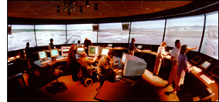
Flying the Friendly Skies Requires Close Monitoring of Air Traffic
 Peak air travel times in the United States see about 50,000 aircraft operating in our skies each day, not counting the tens of thousands of airborne vehicles the world over. It’s no small task for the 15,000 air traffic controllers in airports across the country to prevent these aircraft from colliding into each other.
To ensure the safe passage of 700 million people every year, the dedicated men and women in the air traffic industry must coordinate the movements of thousands of airplanes, from commercial airliners to cargo jets to military transports. Keeping all of these planes at a safe distance from each other, directing them during takeoff and landing at airports, and routing them around bad weather requires monitoring equipment that won’t fail…because the margin for error is zero.
Whether your need is for an ATC display system or avionic software testing and development, we have the in-house expertise to see the job through. Use the contact form or call 800.952.2535 to tell us about your requirements.