Enhancements Overview
Each LCD, OLED and Plasma display part number, without regard to manufacturer or size, has its own unique “personality” pertaining to optical performance. General Digital Optical Bonding Laboratories understands this challenge and has successfully implemented test and characterization methods. This allows us to better understand the display’s capabilities and potential for improvement. We have on our premises an Optical Characterization Laboratory for obtaining photometrics on any given flat panel display.
Luminance
In our Optical Characterization Laboratory, General Digital Optical Bonding Laboratories obtains brightness metrics of your display under dark room conditions and three different simulated daylight conditions. We then do an evaluation of the OEM films in the LCD, OLED or Plasma display and provide analysis on the best configuration based on your expected operating condition. We perform multiple iterations of backlight film modifications and submit the data to you, along with our analysis of what the metrics indicate.
Contrast
In addition to our luminance measuring, General Digital Optical Bonding Laboratories also provides you with empirical contrast ratios based on the multiple lighting conditions utilized in the luminance measuring process. This assists in the decision process of which configuration will best suit your application.
Benefits
- Increase brightness up to 100% with brightness enhancement films alone
- Improve display contrast and readability
- Improve display clarity and image quality
- Superior uniformity
- Improved operating temperature range and brightness
Options
General Digital Optical Bonding Laboratories offers both passive and active backlight modifications to improve sunlight readability. Our most efficient and cost-effective solution is the GenFlective display, a hybrid of transflective and passive enhancements. We also offer a standard transflective display, which incorporates a highly reflective backlight that reflects ambient light back out of the display. Thirdly, we provide the traditional value-add backlight solution, an active enhancement featuring your choice of LED or NVIS backlight technology.
Passive Enhancements
- Consider our own GenFlective™ Technology (PDF)
- Requires no more power than OEM panel
- Dissipates no more heat than OEM panel
- Simplifies integration of value-add display
- Easier to address cooling due to low power
- Can often be combined with other passive enhancements (optical bonding) or active enhancements (sunlight/daylight readable backlights/edge lights)
- Typical enhancement of OEM luminance of 20% to 100%
- Contrast enhancement typically measured in orders of magnitude rather than percentages
 A GenFlective-enhanced LCD, OLED or Plasma display is a display that General Digital Optical Bonding Laboratories has altered, using passive enhancements, to improve the brightness (transmissive and/or reflective) and/or the contrast of the display. Although each display has its own personality, due to differences in design, manufacturing techniques and in the stock film stack, we can typically enhance the performance of an OEM panel utilizing Optical Management Films, Polarizers and Diffusers, and a multitude of films and coatings (Contrast Enhancement, Index Matched, Antireflective, etc.).
 General Digital Optical Bonding Laboratories characterizes your display under dark room conditions and three different simulated daylight conditions. We then do an evaluation of the OEM films in the LCD, OLED or Plasma display and modify this configuration as we deem reasonable. We will do up to four iterations of backlight film modifications and submit the data to you, along with our analysis of what the data tells us.
Transflective Panels
- Although they are designed to reflect ambient light back out the display to augment its performance in direct sunlight, transflective panels have insufficient transmissive luminance (typically ~200 nits) to be considered usable in diffuse lighting conditions where direct sunlight is not available (e.g., cloudy or rainy days).
- Additionally, transflective panels are only available in a limited range of display sizes and resolutions.
Active Enhancements
As more of today’s applications require brighter displays, the shortcomings of CCFL backlights become more apparent. In response to this challenge, LED backlighting has been developed to achieve and maintain the required brightness levels of today’s displays.
Advantages of LED Backlights:
- Sunlight readable, standard luminance, NVIS-compatible options available
- CCFL edge rail replacement with LED or complete light box redesign options
- High color gamut achievable with high power LED
- Lower EMI (Electromagnetic Interference) Emissions
- Lower Power Consumption
- Extended Life Expectancy
- Lower Heat Emissions
- Potentially Lower-Profile-Than-Typical Backlight Replacement Techniques
- GD design meets MIL-DTL-901E, MIL-STD-810F, MIL-STD-461E
- Readily dimmable to very low levels without flicker
- Wide thermal range without heaters
- Any size, any panel, any brightness – Below are a few sample configurations equipped with LED backlights to enhance sunlight readability.
General Digital’s extensive variety of monitor kits and industrial-/military-grade monitors provide our customers with a solution for virtually any type of application or environment.
In addition to being able to request integration of our NVIS- and NVG-compatible LED backlit LCDs into our monitor products, customers may also request the integration of our sunlight readable backlit LCDs, OEM LCDs with LED backlights or third-party enhanced LCDs.
Please feel free to contact a Sales Engineer contact a Sales Engineer to discuss your options and configuration requirements.
GenFlective Technology
As more and more flat panel displays (LCD, OLED, Plasma) find their way into outdoor applications, the need becomes far greater for them to not only be able to withstand severe temperature extremes (heat and cold) and solar radiation, but the display must also be readable when exposed to extreme optical conditions such as direct and indirect sunlight, glare and reflection.
Download GenFlective white paper
Most off-the-shelf displays are not properly equipped to handle all of these requirements. The traditional approach demands installation of value-add backlights to boost brightness and incorporation of thermal management solutions to dissipate the heat generated by the backlights.
Additionally, although transmissive panels are now available with a white luminance of more than 400 nits, they do not provide adequate brightness or contrast to be considered practical in high ambient lighting conditions or direct sunlight.
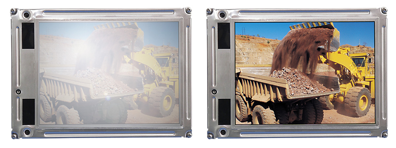
The Myth
It is a common myth that increasing a display’s backlight brightness alone will make it usable in high brightness environments (i.e., sunlight readable). The reality is that the increase in brightness is only a benefit if it does not adversely affect the contrast at the same time.
For example, imagine that a value-add backlight is used to increase the luminance of an OEM display that has a white luminance of 200 nits and a contrast ratio of 300:1 (black luminance of 0.66 nits) by ten-fold to a white luminance of 2,000 nits. While the display is unarguably brighter, the increased brightness will not be of much value in direct sunlight if the “black luminance” is correspondingly increased from 0.66 nits to 660 nits (contrast ratio of 3.03).
These factors, as well as other integration issues such as power consumption and heat dissipation, must be considered as a collective when designing a display for true sunlight readability.
General Digital offers three types of sunlight readable solutions. The first is the traditional value-add backlight solution. The second approach is to provide a transflective display which incorporates a highly reflective backlight that reflects ambient light back out of the display. Our third offering, and generally the most efficient and cost-effective solution, is the GenFlective display, a hybrid of transflective and passive enhancements.
Value-Add Backlights
Traditionally, value-add backlights have a short life expectancy; bulbs generally have a brightness half-life of 20,000 hours, which means that the backlight will only be able to produce approximately half of its original brightness after 20,000 hours. Compared to this, current OEM backlights often are rated for 50,000 hours.
A typical 2,000 nit backlight for a 10.4″ display will require as much as 20 watts, while a 600 nit 20″ backlight uses greater than 60 watts. Because of this high power consumption, heat dissipation is of paramount importance. Integration of thermal management such as heat sinks, cooling fans, heat exchangers, heat pipes, etc. is necessary to maintain safe operating conditions.
Although most recent value-add backlight designs do not add significant depth to the OEM display, they typically require more space in the integrated enclosure due to the necessity to provide thermal management.
By themselves, value-add backlights can be quite costly. In addition to the expense of the backlights and their associated electronics and packaging, most displays also require some optical films as well. When considering the integration of a value-add backlight, one must also consider the expense of the thermal management solution (typically required) as well as the increased cost of ownership resulting from shortened lamp life. And don’t forget about the special inverter(s) required to drive the backlights.
Transflective Panels
Although they are designed to reflect ambient light back out the display to augment its performance in direct sunlight, transflective panels have insufficient transmissive luminance (typically ~200 nits) to be considered usable in diffuse lighting conditions where direct sunlight is not available (e.g., cloudy or rainy days).
Additionally, transflective panels are only available in a limited range of display sizes and resolutions.
GenFlective Technology
A GenFlective-enhanced LCD, OLED or Plasma display is one that General Digital has altered, using passive enhancements, to improve the brightness (transmissive and/or reflective) and/or the contrast of the display. Although each display has its own personality, due to differences in design, manufacturing techniques and in the stock film stack, General Digital can typically enhance the performance of an OEM panel utilizing Optical Management Films, Polarizers and Diffusers, and a multitude of films and coatings (Contrast Enhancement, Index Matched, Antireflective, etc.).
In contrast to value-add backlights, displays enhanced with GenFlective technology do not require any additional power since General Digital has not modified the OEM bulbs, backlights or LEDs. In addition to reduced power consumption, this benefits the end user with cooler running units, which in turn negates the need for bulky, complex and/or expensive cooling systems (fans, heat exchangers, heat pipes, etc.) that traditional value-add backlights typically require. Another benefit resulting from these factors is improved reliability (reduced piece count).
Since the display’s lamps are not being overdriven, the GenFlective enhancements do not adversely affect the brightness half-life of the bulbs. A direct correlation exists between the brightness half-life of the bulbs and the suitability and cost of ownership of the integrated solution. For example, most bulbs are rated for 50,000 hours when operated at their intended drive current. As a rule of thumb, the bulbs will lose 10% of their initial brightness during their first 500-2,000 hours and 1-5% for every 1,000 hours of use thereafter. Longer brightness half-life also reduces the cost of ownership by reducing the frequency in which the backlights must be replaced.
In theory, candidate displays for GenFlective enhancement can be of any size, resolution or manufacturing origin. The success of the candidate display is most influenced by the display’s aperture, transmissivity and the “personality” (OEM film recipe).
Combining GenFlective with Other Technologies
To further enhance LCD performance and improve its ruggedness, GenFlective technology can be combined with optical bonding, provided by General Digital’s Optical Bonding Laboratories.
Optical bonding of an LCD reduces internal reflection and increases brightness and contrast by index matching internal surfaces. It also creates a shatterproof construction similar to the properties of automotive windshields. An additional benefit is the optical-friendly integration of other options, such as heaters, EMI filters, hot mirrors (IR filters) and more.
Another combination utilizes low power active enhancement, which allows overdriving of cold cathode fluorescent tubes and multiple tube edgelight replacements.
Overdriving the bulbs, or using a drive current that is greater than recommended by the OEM manufacturer, will increase display brightness but will also reduce the brightness half-life expectancy of the bulbs. Increasing the number of bulbs will also increase the luminosity of the panel and add less than 10 watts of additional power consumption.
In some instances, GenFlective technology can also be combined with traditional value-add backlights for a “best of both worlds” solution.
Integration Decisions and Influences
To optimize the benefits and performance of the GenFlective-enhanced LCD, OLED and Plasma display panels, General Digital recommends that an index-matched-to-air antireflective coating be included on the outer viewing surface to improve contrast. Customers should note that special handling and cleaning instructions are required for the care of antireflective coatings.
Introduction of overlays that adversely affect light transmission, such as vandal shields, touch screens, EMI filters, hot mirrors, etc., will diminish the performance of the Genflective-enhanced flat panel display.
Film Lamination
Overview
Light emitting displays, including LCD, OLED, Plasma and other technologies, all suffer from a visibility problem when used under conditions which include high ambient lighting levels. A common condition is exposure to uncontrollable outdoor lighting, such as kiosks, advertising displays, control towers and aircraft cockpits, to name just a few. The solution is to increase the luminance of the display well above normal levels expected for indoor use. The display contrast must be increased to maximum, as well. Because of these measures, precautions must be taken to avoid direct specular reflections from the display surface.
Several technologies have been developed to improve the situation. One of these technologies is film lamination. General Digital Optical Bonding Laboratories can passively enhance a display by applying optical films to its front surface, thereby improving brightness and contrast by reducing surface reflections.
General Digital Optical Bonding Laboratories is a National Distributor of Tigold Films (formerly known as OCLI). We also integrate films from other third party film manufacturers.
Antireflective Film (AR)
- Laminated to the front surface of the LCD panel. Can be performed either directly in-the-frame or under-the-frame. General Digital prefers the under-the-frame method to reduce risks of delamination.
- Reduces surface reflections, thereby improving brightness and contrast two to three times without actually making display brighter.
Antireflective Film and Antiglare Film (AR)
- Laminated to the front surface of the LCD panel. Can be performed either directly in-the-frame or under-the-frame. General Digital prefers the under-the-frame method to reduce risks of delamination.
- Reduces surface reflections, thereby improving brightness and contrast two to three times without actually making display brighter. Softens direct light source images in reflection.
Conductive Films (EMI/RFI Reduction)
-
- Laminated to the front surface of the LCD, OLED or Plasma panel. Can be performed either directly in-the-frame or under-the-frame. General Digital prefers the under-the-frame method to reduce risks of delamination.
- Reduces EMI emissions.
Specialty Films
- Reduces reflected ambient light more than the emitted light, thereby increasing contrast of the display.
Color Selective Films
- Alters the output color of the screen. Can be used to trim the output for special applications.
For further information regarding optical film enhancements or to request a quote for your application, please contact one of our qualified Sales Engineers.
Sunlight Readable LCD Displays from General Digital
Selecting an LCD monitor for “daylight” jobs isn’t an easy task. But don’t worry–it’s not your fault. On most typical flat screen computer monitors, the LCD panels only produce between 200 and 350 nits of backlighting. For daylight and sunlight readability, this is not enough luminance to create the high contrast necessary to make monitor displays visible against glare.
Daylight Readable and Sunlight Readable LCD technology takes backlighting to the next level. In order to be properly viewable during the day, whether outdoors or indoors in high ambient lighting, General Digital configures its daylight readable flat panel screens to produce at least 343 nits of luminance. To guarantee color visibility in direct sun, our sunlight readable flat panel displays produce at least 686 nits of luminance.
Thanks to extra effort and extensive research into outdoor display visibility, General Digital has created a set of industry-leading high brightness monitors. Most of our display products are engineered go wherever you need them and work flawlessly for years—decades even.
With some models UL and FCC certified and upholding the standards of military requirements, General Digital’s monitors with the sunlight or daylight readable option are high quality and durable.
Select a sunlight readable monitor below that will best suit your needs. Mousing over the product name reveals a photo and brief description, and the link takes you to a page with detailed information.
Enhanced Light Guide
General Digital Optical Bonding Laboratories is well qualified to enhance your existing LCD, OLED, Plasma or other display type. We can also provide a complete flat panel package, ready to drop in right out of the box.
General Digital has designed dozens of value-add LCD displays, featuring our NVIS LED backlights (edge-lit and direct-lit), light optimization films and optical enhancements/overlays.
While General Digital’s enhanced displays are available for purchase as a component (display only), they are also available for integration into most of our standard LCD monitor products and custom products, including:
LED Backlight Monitors: Specifications
Below, General Digital has provided a sampling of fully integrated Sunlight Readable Monitors that feature our enhanced displays found on the LED BACKLIGHT DISPLAYS: SPECIFICATIONS tab. These examples are provided to illustrate how our Sunlight Readable Displays can be integrated into General Digital’s standard family of products, or into a custom configuration. Please note that most of these products feature LED backlights, and some are NVIS-compatible. Links have been provided to data sheets, photometric data and control drawings. Please feel free to contact a Sales Engineer to help you understand these test results or answer your questions.
Click the Part Number to page down to the specifications for that monitor.
| Part Number | Model Number | Product Family | Display Size (Diag.) | Native Resolution (Pixels) | Data Sheet | Control Drawing |
|---|---|---|---|---|---|---|
| 90-3240-010 | SGD-24D-999-46-00-18-58-IP29-121 | Saber Standalone Solar/LS24 | 24.0" | 1920 x 1080 WUXGA | Download | Download |
| 90-3215-005 | SGD-22D-987-46-00-18-58-IP29-121 | Saber Standalone Solar/LS22 | 21.5" | 1920 x 1080 WUXGA | Download | Download |
| 90-850-168 | UB-21U-995-dd-00-01-gg-EAjj | GenStar III | 21.3" | 1600 x 1200 UXGA | Download | Download |
| 90-850-150 | SGD-20U-979-40-00-16-41-EP11 | Saber Standalone Solar/LS20 | 20.1" | 1600 x 1200 UXGA | Download | Download |
| TBD | UB-19W-992-dd-00-01-gg-EAjj | GenStar III | 19.0" | 1280 x 1024 SXGA | Download | Download |
| 90-850-115 | SNCMP-19W-967-61-00-51-25-EP27-077 | Saber PanelMount Solar NVIS | 19.0" | 1280 x 1024 SXGA | Download | Download |
| 90-967-001 | SNBP-17W-956-76-00-15-69-ID52-153 | Barracuda PanelMount Solar NVIS | 17.0" | 1280 x 1024 SXGA | Download | Download |
| 90-915-020 | SCMP-15X-954-32-00-01-35-0092-070 | Saber PanelMount Solar | 15.0" | 1024 x 768 XGA | Download | Download |
| 90-959-007 | SNBS-15X-938-73-00-15-66-SA39-137 | Barracuda Standalone Solar NVIS | 15.0" | 1024 x 768 XGA | Download | |
| 90-713-014 | SNSL1-15X-939-32-69-02-04-0092 | SlimLine 1U Solar NVIS | 15.0" | 1024 x 768 XGA | Download | |
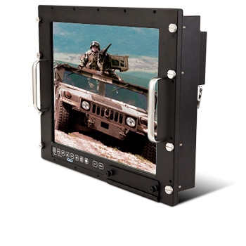
| 90-911-023 | SRH-15X-955-60-00-23-04-0092 | Rack Mount Hinge Solar | 15.0" | 1024 x 768 XGA | Download | |
| 90-450-021 | SNMK-06X-908-77-00-00-82-0092-160 | Impact Solar NVIS | 6.5" | 1024 x 768 XGA | Download | |
| 90-3064-012 | SNBS-06V-907-71-00-15-04-SA31-000 | Barracuda Standalone Solar NVIS | 6.5" | 640 x 480 VGA | Download |
Saber Standalone Solar/LS24
VESA Mount Sunlight Readable 24.0″ LCD Monitor

- Sunlight readable LCD monitor with LED backlight (Display Model #999)
- 24.0 inch, 1920 x 1080 WUXGA resolution
- Maximum brightness programmable up to 700+ nits
- Low power, long life, LED backlight
- 0% to 100% backlight dimming
- Surface Capacitive Touch Screen Overlay
- Antiglare etch and antireflective coating (specially selected for Air Traffic Control Tower Applications)
- Optically bonded to LCD to minimize internal reflections, maximize contrast, and create a vandal shield for the display
- Industrial-grade, Aluminum Enclosure
- Supports VESA mounting
- Front accessible silicone OSD with programmable brightness LED backlights
- Speaker for alarm annunciation
- Optional Panel Mount Adaptor Bracket
- Smart Fan Controller
- Automatically controls fan activation and fan speed to reduce noise
- Integrated Power Supply
- Power factor correction
- Compliant with FAA-G-2100-H for harmonics and current limiting
- Connectors
- Analog VGA: DE-15 Socket
- HDMI: 19-pin Plug
- DVI-D: 30-pin Micro Cross Socket
- Programming Port: DE-15 Plug
- Power: IEC-320 AC Plug with On/Off rocker switch
- Touch: DE-9 Socket
- Operating temperature: 0° C to +50° C
Saber Standalone Solar/LS22
VESA Mount Sunlight Readable 21.5″ LCD Monitor
Part Number 90-3215-005
- Sunlight readable LCD monitor with LED backlight (Display Model #987)
- 21.5 inch, 1920 x 1080 WUXGA resolution
- Maximum brightness programmable up to 650+ nits
- Low power, long life, LED backlight
- 0% to 100% backlight dimming
- Surface Capacitive Touch Screen Overlay
- Antiglare etch and antireflective coating (specially selected for Air Traffic Control Tower Applications)
- Optically bonded to LCD to minimize internal reflections, maximize contrast, and create a vandal shield for the display
- Industrial-grade, Aluminum Enclosure
- Supports VESA mounting
- Front accessible silicone OSD with programmable brightness LED backlights
- Speaker for alarm annunciation
- Optional Panel Mount Adaptor Bracket
- Smart Fan Controller
- Automatically controls fan activation and fan speed to reduce noise
- Integrated Power Supply
- Power factor correction
- Compliant with FAA-G-2100-H for harmonics and current limiting
- Connectors
- Analog VGA: DE-15 Socket
- HDMI: 19-pin Plug
- DVI-D: 30-pin Micro Cross Socket
- Programming Port: DE-15 Plug
- Power: IEC-320 AC Plug with On/Off rocker switch
- Touch: DE-9 Socket
- Operating temperature: 0° C to +50° C
Saber Standalone Solar/LS20 Sunlight Readable 20.1″ LCD Monitor
Mountable Sunlight Readable 20.1″ LCD Monitor

Part Number 90-850-150
- Sunlight readable LCD monitor with LED backlight (Display Model #979)
- 20.1 inch, 1600 x 1200 UXGA resolution
- Maximum brightness programmable up to 800 nits
- Low power, long life, LED backlight
- 0% to 100% backlight dimming
- Surface Capacitive Touch Screen Overlay
- Antireflective film mounted to rear to minimize internal reflections
- Industrial-grade, Aluminum Enclosure
- Supports VESA mounting
- Front accessible silicone OSD with programmable brightness LED backlights
- Speaker for alarm annunciation
- Optional Panel Mount Adaptor Bracket
- Smart Fan Controller
- Automatically controls fan activation and fan speed to reduce noise
- Integrated Power Supply (externally mounted)
- Power factor correction
- Auto power-on
- Connectors
- Analog VGA: DE-15 Socket
- NTSC: BNC
- DVI-D: 30-pin Micro Cross Socket
- Power: IEC-320 AC Plug with On/Off rocker switch
- Touch: DE-9 Socket
- Operating temperature: 0° C to +50° C
- Download the Data Sheet
- Download the Control Drawing
Barracuda PanelMount Solar NVIS 17.0

Waterproof Outdoor Sunlight Readable 17.0″ LCD Monitor with NVG Compatibility
Part Number 90-967-001
- Sunlight readable and NVIS-compatible LCD monitor with LED backlight (Display Model #956)
- 17.0 inch, 1280 x 1024 SXGA resolution
- Maximum brightness limited to 600 nits to conserve power/heat
- Low power, long life, LED backlight
- 0% to 100% backlight dimming
- Glass-Film-Glass resistive touch sensor with antireflective coating
- Includes circular polarizer and 1/4-wave retarder for maximum contrast
- Includes EMI mesh for improved emissions
- Optically bonded to LCD to minimize internal reflections, maximize contrast, and create a vandal shield for the display
- Industrial-/marine-/military-grade IP67 panel mount enclosure
- MIL-STD-810G 512.5 Procedure I/IP67
- 10-button silicone keypad, LED backlit
- NVIS/daylight buttons
- Environmentally-sealed connectors (MIL-DTL-38999 style)
- DVI: MIL-DTL-38999
- Touch screen (USB): MIL-DTL-38999
- Power: MIL-DTL-38999
- Input power: +16 to +75 VDC
- Operating temperature: -20° C to +50° C
- Designed to meet EMI per MIL-STD-461F: CE-1010/CE-102/CS-114-1 (curves #2 & #5)/CS-116/RE-101 (RE-102-1)/RE-102 (RE-102-1)/RS-103
- Download the MIL-STD-3009 Photometric Data for Display Model #956
- Download the Control Drawing
Saber PanelMount Solar 15.0
Sunlight Readable 15.0″ LCD Monitor

Part Number 90-915-020
- Sunlight readable panel mount LCD monitor with an LED backlight
- 15.0 inch, 1024 x 768 XGA resolution
- 1000 nit maximum brightness
- Low power, long life, LED backlight
- 5% to 100% backlight dimming
- Surface capacitive touch screen with ideal etch finish
- Industrial-grade enclosure with panel/console mount bezel
- 7-button, tactile keypad with LED backlighting
- Panel mount waterproof gasket
- Connectors
- Analog VGA: DE-15 Socket
- NTSC Video: BNC Socket
- Touch: DE-9 Socket
- Power: 2W2 Socket
- Input power: +12 VDC
- Operating temperature: 0° C to +50° C
- Download the Data Sheet
Barracuda Standalone Solar NVIS 15.0
Waterproof Outdoor Sunlight Readable 15.0″ LCD Monitor with NVG Compatibility
Part Number 90-959-007

- Sunlight/daylight readable and NVIS-compatible LCD monitor with LED backlight (Display Model #938)
- 15.0 inch, 1024 x 768 XGA resolution
- Maximum brightness limited to 600 nits to conserve power/heat; 20 nits for NVIS mode
- Low power (8 watts), long life, LED backlight
- 0% to 100% backlight dimming
- Glass-Film-Glass resistive touch sensor with antireflective coating
- Includes circular polarizer and 1/4-wave retarder for maximum contrast
- Optically bonded to LCD to minimize internal reflections, maximize contrast, and create a vandal shield for the display
- Industrial-/marine-/military-grade IP67 standalone/mountable enclosure
- 10-button tactile keypad
- NVIS/daylight buttons
- 10-button tactile keypad
- Environmentally-sealed connectors
- DVI: LTWHJ-19PFFR-QS7001
- Touch screen (USB): Type A
- Power: 2W2 socket
- Analog VGA: DE-15 socket (x2)
- NTSC: TNC jack (x2)
- Input power: +9 to +36 VDC (maximum power consumption = 50 watts)
- Operating temperature: –20° C to +60° C
- Accessories: External AC/DC power supply with sealed 2W2 connector (plug)
SlimLine 1U Solar NVIS 15.0
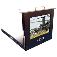
Sunlight Readable Flip-up 15.0″ LCD Monitor/Keyboard with NVG Compatibility
Part Number 90-713-014

- Sunlight/daylight readable and NVIS-compatible LCD monitor with LED backlight (Display Model #939)
- 15.0 inch, 1024 x 768 XGA resolution
- Maximum brightness limited to 600 nits to conserve power/heat; 20 nits for NVIS mode
- Low power (8 watts), long life, LED backlight
- 1% to 100% backlight dimming
- Double-sided glass overlay
- Industrial-/military-grade rack mount flip-up display with integral keyboard and trackball
- 82-key, USB, military-grade keyboard with NVIS compatible backlit keys
- Connectors
- Analog VGA: DE-15 Socket
- Keyboard/Trackball: DE-9 plug
- Power: 6-pin Hirose circular
- Input power: +12 VDC (maximum power consumption = 30 watts)
- Operating temperature: -10° C to +50° C
- Download the MIL-STD-3009 Photometric Data for Display Model #939
Rack Mount Hinge Solar 15.0
Sunlight Readable Flip-up 15.0″ LCD Monitor
Part Number 90-911-023

- Sunlight readable flip-up/-down LCD monitor/keyboard with LED backlight
- 15.0 inch, 1024 x 768 XGA resolution
- 1500 nit maximum brightness
- Low power, long life, LED backlight
- 0% to 100% backlight dimming
- Double-sided antireflective glass overlay
- 1U (1.75″ high) industrial-grade rack mount flip-up display
- Drip proof from the front
- 20″ slides with 5.5″ extension
- Connectors
- Analog VGA: DE-15 Socket
- NTSC Video: BNC Socket
- DVI: DVI-I Socket
- HDMI: HDMI Socket
- S-Video: 4-pin Mini-DIN Socket
- Power: 2W2 Socket
- Input power: +12 VDC (maximum power consumption = 25 watts)
- Operating temperature: 0° C to +50° C
- Download the Data Sheet
Impact Solar NVIS 6.5
Sunlight Readable 6.5″ LCD Monitor Kit with NVG Compatibility
Part Number 90-450-021

- Sunlight readable open frame LCD monitor kit with LED backlight
- 6.5 inch, 1024 x 768 XGA resolution
- Maximum brightness of1000 nits
- Low power, long life, LED backlight
- 2% to 100% backlight dimming
- Chemically strengthened glass vandal shield with AR coating
- Optically bonded to reduce internal reflections and improve contrast in high ambient lighting conditions
- Industrial-grade open frame monitor kit
- Keypad attached to rear cover
- Connectors
- Video: Compact Flash Card for MPEG Video
- Power: Waterproof DC Barrel Socket on 6″ pig tail (interfaces to Batterspace Battery Pack)
- Input power: +12 VDC (Maximum Power = 21W)
- Operating temperature: –0° C to +50° C
- Includes external switch cable (buttons 1 and 2) from the media player
- Download the MIL-STD-3009 Photometric Data for Display Model #908
Barracuda Standalone Solar NVIS 6.5
Outdoor Sunlight Readable 6.5″ LCD Monitor with NVG Compatibility
Part Number 90-3064-012

- Sunlight readable and NVIS-compatible LCD monitor with LED backlight (Display Model #907)
- 6.5 inch, 640 x 480 VGA resolution
- Maximum brightness limited to 700+ nits to conserve power / heat
- Low power, long life, LED backlight
- 0% to 100% backlight dimming
- Double-sided antireflective glass overlay
- Industrial-/marine-/military-grade IP67 standalone/mountable enclosure
- 10-key membrane keypad
- NVIS/daylight buttons
- 10-key membrane keypad
- Environmentally-sealed connectors
- DVI: DVI-D socket
- Analog VGA: DE-15 socket
- Power: 2W2
- Composite: BNC socket with dust cap
- Input power: +12 VDC (maximum power consumption = 15 watts)
- Operating temperature: -20° C to +50° C
- Includes external +12 VDC output, 90-264 VAC input power supply
- Download the MIL-STD-3009 Photometric Data for Display Model #907
Documentation
All documents will open in a separate browser window.
Data Sheet
![]() Sunlight Readable/NVIS Dual LED Driver for LCDs Data Sheet 999-0421-406
Sunlight Readable/NVIS Dual LED Driver for LCDs Data Sheet 999-0421-406
Presentation
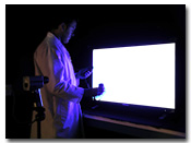
![]() MIL-STD-3009 Sunlight Simulation and Measurement Test Setup
MIL-STD-3009 Sunlight Simulation and Measurement Test Setup
White Papers
![]() Not All Brightness Is Created Equal – A Discussion of LCD Brightness Values for the Real World
Not All Brightness Is Created Equal – A Discussion of LCD Brightness Values for the Real World
![]() Déjà Vue – Finding a Better Path to Specifying an Enhanced LCD to Meet Your RFQ
Déjà Vue – Finding a Better Path to Specifying an Enhanced LCD to Meet Your RFQ
![]() LED Backlights Improve Performance and Longevity of Sunlight Readable NVIS-Compatible Displays
LED Backlights Improve Performance and Longevity of Sunlight Readable NVIS-Compatible Displays
![]() Weber Contrast Class – The True Measure of Sunlight Readable Displays
Weber Contrast Class – The True Measure of Sunlight Readable Displays
Temperature and Humidity Testing Available on Contract
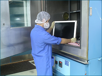
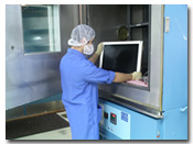
In response to the challenging needs of our diverse customer base, General Digital Optical Bonding Laboratories provides on-site thermal and humidty testing and data logging services. Many customers find themselves faced with meeting strict military, industrial, or harsh environmental requirements. Some of these requirements include
- MIL-STD-810F (paragraphs 501.4, 502.4, 507.4)
- ESS (Environmental Stress Screening)
- Solar Loading (for use in direct sunlight)
As more and more LCDs, OLEDs and Plasma displays find their way into outdoor applications, the need becomes far greater for them to not only be able to withstand severe temperature extremes (heat and cold) and solar radiation, but the flat panel display must also be readable when exposed to extreme optical conditions such as direct and indirect sunlight, glare and reflection. On an average sunny day, the illumination of ambient daylight is approximately 30,000 nits. Therefore, brightness should be over 900 nits to get a clear image for an outdoor application.
Most off-the-shelf LCDs, OLEDs and Plasma displays are not properly equipped to handle all of these requirements. General Digital Optical Bonding Laboratories offers several brightness enhancement solutions to meet/exceed our customer’s requirements.